Tuesday, June 26, 2012

N64 Overclock: Heatsink- Part 4

Okay, first off, I would like to say that not everything goes according to plan. There were several times throughout the course of this mod that I was forced to alter my plan and do something else. I will do my best to explain why I wanted to do certain things, and why not all of them worked. That being said, I did successfully mount a pretty awesome heatsink in the N64, and it works great. So if you are interested in how I did that, keep reading.

Some general points to cover. 
-First, if you plan on using a fan, plan the airflow through the N64. If the fins on the heatsink are going the wrong way, you might not get good enough airflow across the heatsink. So make sure you are going to be able to get air where you want air. It's pretty cramped in the case, so it's worth coming up with a good plan before you buy anything or cut anything.I wanted one piece of heatsink to cover the CPU, RCP and onboard memory. 
-Secondly, I wanted the heatsink to directly contact those chips, but that ended up not being easy (the chips aren't all at the same height). Because I thought I was going to be able to go straight the tops of the chips to the bottom of the case, the piece of heatsink I started with wa60 x 150 x 25 mm, (L,W,H) and made of aluminum. (you can find it here) This ended up being almost too tall. To properly cover tall three chips on the mobo you are going to have cut the heatsink some way, because you can't go straight from the bottom of the memory chip to the CPU without running into the power switch (or your overclocking switches). So I opted to just trace the bottom edge of the original heatsink onto the new one.
Like this.
 Right here (already) I made my first mistake. I decided to drill holes through the heatsink so that I could screw through it into the original heatblocks, which ended up not being possible due to the fins from the heatsink contacting the screws. If you have some magic way to drill through heatsink fins without breaking drill bits (maybe a drill press?) more power to you. I didn't, so the next pictures show me drilling holes that I couldn't use.
At least I put them in the right places.


It *looks* like a good plan.


Before I drilled any holes, I decided to cut the heatsink profile. I decided it only needed to be cut on the one side, and that the other side wouldn't hit anything. To cut it, I used a jigsaw with a metal bit. Historically, I don't get along very well with jigsaws. Additionally, the fins made the cutting super hard. I got the the job done, but it wasn't pretty, and I cut my self a couple times (from holding the aluminum, not the blade). So if you see any blood in the following pictures, don't freak out. Also, obviously, you aren't going to be able to turn the jigsaw blade in solid aluminum, so plan accordingly (aka: straight cuts).
Looking okay so far.
 My jigsaw cut kinda crooked, because the blade may have not been perfectly straight, so I used a dremel to clean the angles up. I suggest having a couple cutting blades and a good grinding bit.
it looks innocent, but it's just waiting to eat 4 hours of your time and one of your fingers
 I spent the majority of the time trimming the heatsink in various places so that it would fit in the case. The basic profile fit, but it contacted several places (mostly on the top half of the case) preventing it from being mounted. I'll try to list all the places to watch out for.


First, the heatsink was hitting the plastic Expansion/Jumper Pack slot, so I actually just cut that off the case (because I knew it wouldn't hit the actual Expansion Pack). Plus, I needed better airflow to the Expansion Pack.
Just like that.
Secondly, because I had my heatsink shifted left (not centered) I had to trim down 4 of the fins on the left. I just made angled cuts, and it fit.
Seen here on the left.
Thirdly, the plastic from the "Reset" button on the 64 hangs down farther than you probably noticed (that button gets ignored most of the time). I had to cut a cubic section out of 4 fins on the right side of the heatsink. You can see this in the previous picture, and will probably notice it in later pictures as well.

Then, I recommend taking a break from cutting aluminum. I took a minute or two to solder in a switch for the case fan. I did this pretty quicky, just clipping the positive wire, stripping it, and then soldering in the switch right there.


Clip
Strip
Switch.
Once again, the heatshrink got hot prematurely (due to proximity to the solder) and was a waste. I then made a corresponding hole in the top of the case (to the left of the power switch), complete with the little counter hole to keep the switch from spinning. 
as seen here
and here.

Back to the heatsink. I mentioned earlier that I had difficulty drilling holes for screws due to the fins. I very much did.
I actually broke this drill bit twice.
As good as the holes looked, due to the fins, my own error, and other factors they were pretty much completely worthless, and didn't even match up very well.
stupid.
So, I came up with a new method for keeping the heat blocks,
pictured here (the big silver squares)
Pressed against the new heatsink. Once again, I'm sure there are many ways to do this, and feel free to do whatever you can do best. I chose to learn a new skill- drill and tap threads into the heatblocks,
with this handy kit
and then run screws through the heatsink into the blocks. This actually worked out pretty well. I was able to put the screws through the heatsink between the fins, and they held very firmly. In the end, it looked like this.


notice the smaller holes.
don't forget to thermal paste between the blocks and the heatsink.
This method worked very well, and added a lot of strength to the setup. Obviously, don't forget to remove the heatblocks from the mobo when drilling into them- wouldn't want to accidentally drill into a chip.

I obviously skipped putting the shielding back on the top half, but I could have easily slipped it in there if I wanted to. Personally, I felt it was unnecessary, would make cleaning harder, and might hinder heat transfer. So I left it off.


 So, just to point out, the only screws holding the heatsink assembly to the mobo are two screws going into metal feet that are soldered into the mobo, on either side of the onboard memory. Not as good as I would have liked, but it was very solid, and offered plenty of pressure against the chips.


With the heatsink mounted, it looked like this.
cool, but messy
 I cleaned and thermal pasted everything, and then made sure the case fit on (it did). So, here are some more shots of the final product.
close fit against the Expansion Pack


finally justified the transparent case.
Why weren't they shipped this way?
 So, the final (final) step of my N64 project is mounting the case fan. I'll admit, it's already pseudo mounted, but I want to clean it up a bit before doing a post on it. So, hold tight, and it will probably be posted by the end of the week.


One last thought, save any pieces of the case that you cut off or don't use. You may want to convert those pieces to ABS plastic cement using Acetone, but I'll cover that later. For now, don't throw away any plastic you cut off the case.

Monday, June 25, 2012

Fan Testing and Planning- N64 Overclock Part 3

I'll be honest, this post most likely won't have very much useful information in it. The only technical information provided here is what to solder to if you are interested in wiring up a case fan or anything that you want to run off 12v. 

So, without further adieu, I'll kick this thing off. 

Something to keep in mind- you are probably going to want to be able to open the N64 in the future (and this may be common sense to some of you) but that means you can't just solder up the fan to the 64, if you plan on having the fan be attached to anything you plan on detaching from the mobo. I just mention this, because I get excited easily and would probably screw that up if I didn't think this through beforehand. 

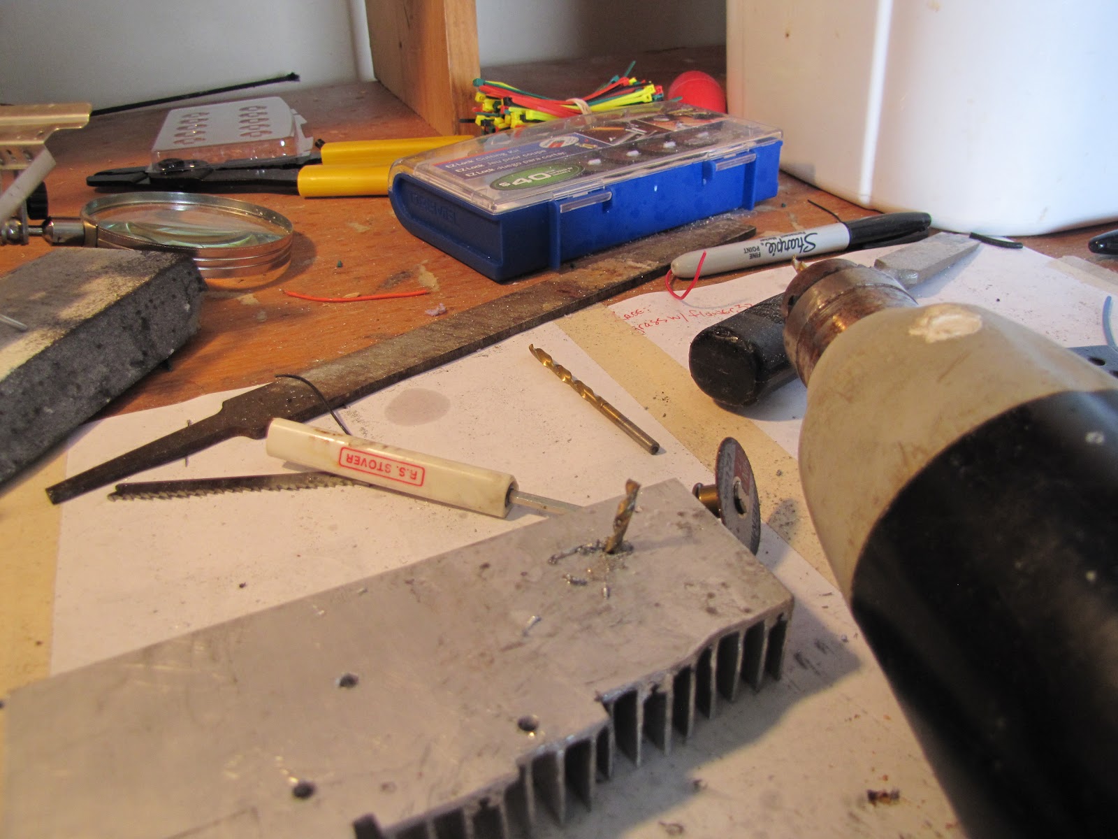
Shown here is my case fan and large heatsink. We are going to be focusing primarily on the fan in this post, so here are it's specs: 60 x 60 x 15mm / 2.4" x 2.4" x 0.6"(L*W*H), Cable Length22cm. I am unsure of the amps, CFM (cubic ft/minute), RPM, wattage etc, because I bought it cheap. So, sorry I couldn't be of more help there.

parts shown here
 So, I decided to open the N64 up and wire in the fan, and just run it for a while (normal clock and overclocked) to ensure that the extra power draw on the 12v line would not cause any problems. "What problems?" you may be asking. Well, here are some theoretical (because none of this is documented) problems I came up with - 1. Because the 12v line powers the audio/video out, extra draw could cause loss of signal strength resulting in picture/sound distortion, etc 2. The extra draw on the 12v could cause extra stress on the stock N64 power supply, eventually leading to an overheat. Those are what I came up with.
Top shell off.

Instead of taking all of the heatsink and shielding off of the mobo, I was pretty sure I could just solder to the bottom of the mobo, so I just lifted the whole board (sans bottom shielding) out of the case.

like this.
 So, then I began examining the bottom of the mobo. Previously, I had marked the ground going to the power supply with a black sharpie, as you can see on the top right corner of the board (right where the plastic connector is)
Those 3 pins
Any of those three pins should work as ground. Now, the 12v line should be labeled. There are little white stamps on the 64 that tell you what is what for a little bit. It can be a little hard to trace that line through the circuitry, so I'll just give you a tip- you want to solder to pin 7 of the power switch.
On the right side of the board, right under the power switch
So, right under the power switch there are 8 pins, numbered 1-8. you want pin 7. You can solder right to it, and it will provide 12v. You could probably grab ground right there too, just figure out which pin it is. I didn't do this, but I had wire to spare, you might not.

 At this point, I began trying to see how the wires would fit under the bottom shielding and wrap around to the top, where it could be connected to the fan.
I ended up not doing it this way.
You can take creative liberty on how you do this. There ended up being enough clearance to pass the wires under the shielding at either end of the side, so I just did that. 

 I then started seeing how the wires would be situated. Total waste of time. I eventually ended up wiring in a switch for the fan, so I left wires long. You can always shorten wires pretty easily, adding to them is more difficult.
In the end, things looked a little different from this.

Anyways, back to the (hopefully) useful information. I soldered my ground to 2 of the 3 ground pins, just for added strength, and also because I'm not sure if all of those ground go to the same thing (I'd think they would).
more is better?
 And then I soldered to pin 7. That's really it. I tried to put on some heatshrink (I do whenever I can), but it got hot enough that it shrunk prematurely.
keeping it petite.
 When I was done, it looked like this.
Not too shabby. 
 Okay, now something I forgot. The shielding on the bottom actually extends a decent way onto the board from the sides. So if you could keep the wires further from the edge of the board, that would be better. I had no problems, but getting the shielding on without smashing/crimping the wires was a little tighter than I would have liked.

Once that was dealt with, I set the mobo back in the shell, and attached parts necessary for a trial run.
first without the fan attached
After testing it without the fan connected, I attached the fan and fired it back up.
It looks cool already.

 I checked out everything. There was absolutely 0 (zero) change to picture/sound quality, and after playing for a while, there was no exceptionally bad heat build up in the power supply.
blah blah blah.
So, some closing thoughts. First off, I ended up wiring in a switch to turn the fan on/off because I wasn't sure how loud it was going to be. That's covered later. Another though, I left the fan blowing on the Expansion Pack's heatsink (seen here), and it stayed chilly chill. It had almost zero noticeable heat buildup after even some overclocked playing, where it used to get hot to the touch after just about 15 minutes. What I'm getting at is simply thus: you could have a great time with your overclocked N64 as long as you perform the before-mentioned Expansion Pack mod and mounted a case fan somewhere to keep the air moving well.

Even so, I decided to go through the grueling process of putting in a more effective heatsink. It is probably massively overkill, but in the end it worked. That post however, will be covered tomorrow hopefully.

N64 Overclock Minor Update (no pictures)

I soldered in the fan, tested out the N64, and everything is running great. Just a little bit of airflow is exactly what the heatsink over the Expansion Pack needs to stay cool. The next thing I'm working on is the large heatsink. Even though everything seemed to run fine with the stock heatsink, I came here to party, and I'm not leaving without a custom heatsink (that is probably three times overkill).

That is the major project, minor steps along the way include potentially mounting another switch to turn the fan on/off (under the idea that I may want to turn it off for some reason), deciding whether or not to keep or ditch the radio shielding, and finally deciding how to mount the fan.

So, at the minimum for today, I plan on wiring in the switch for the case fan and finishing the large heatsink.

Friday, June 22, 2012

Parts Have Arrived

Contrary to my opinions in today's earlier post, pretty much all of the parts arrived in the mail today.


So, the large heatsink required for the N64 mod finally arrived. Even so, I still plan on wiring in the fan first. If the fan doesn't work out, I will have to think about what I'm going to do for heatsinks.


Parts for fixing the iTouch also arrived today. That is deffinately the easier project, so that might get posted first.


So, we'll see how much I get done tonight, and tomorrow before I head in to work. I doubt I'll get much done Sunday because I'll be traveling. AKA: don't expect any serious progress until early next week.

Overclock Update- Still Waiting (Sum41)

I am still waiting on my primary heatsink to arrive, which is very frustrating, as I swear the est delivery date keeps moving back. I guess that's what I get for buying international. Seriously, I think the est d-day is 06/28/12 - 07/12/12. So, yeah.


However, in the meantime, I have plans. I am going to go ahead and at least wire in the case fan, and then test run the N64 with it. The case fan will be drawing power from the 64's 12volt line, which is used primarily for audio/video signals, so I want to make sure it can run under load without causing any picture/sound distortion. Also, the fan will probably be drawing an extra 1-2ish watts from the stock N64 power supply. I'm pretty confident that the 64 power supply can handle it, but if there is going to be an overheating problem or anything else, I want to know before I take all the time to mount this fan to the case.


So, if all of those tests go well, I may go ahead and mount the fan in the case. I've got a pretty good idea of what I want to do in that respect, so I may go ahead and mount it and worry about the heatsink fitting later. In my opinion, there's only one place the fan can go where it will be productive and not look retarded, so if I have to dremel down my heatsink a little later, I'll live with that.


One last thought looking to the future, I may abandon Expansion Pack/Jumper Pack switchability, and just decide to have a permanent Expansion Pack. This would save me a lot of space in the 64's case, in the basic area I am trying to mount this fan. Like I said though, just a thought- I won't have to actually make that decision until I'm done running my fan tests.

Thursday, June 21, 2012

Expansion Pack Mod- N64 Overclock Part 2

Okay, first things first. All that is accomplished in this post is the addition of an aluminum heatsink to an N64 Expansion Pack. Why would you want to do this? Well, have you ever had your N64 lockup on you? Have you ever noticed severe slowdown during a 4-player match of Smash Bros? I have, and as it turns out, the memory in the Expansion Pack is to blame. In general, the default Jumper Pack does not have over-heating issues, but the Expansion Pack can. 

So if you use an Expansion Pack, and have had your N64 lock up on you, get laggy without correlation to CPU lag, or if you plan on overclocking your 64, you might want to consider this mod.

I started off with my 3rd party Expansion Pack (EP from now on). I used a 3rd party one because you can disasseble it with a phillips head screw driver. This goes pretty quick.
took the goofy red cover off
The cuts in the metal are from an earlier attempt to cool the EP

Back plate off
first layer of aluminum shielding off
Once the EP is fully dissembled, you need to start considering a few things. First off, how important is it that you are able to easily remove the EP in the future? I wanted to be able to do this, so I decided to keep the EP memory chip attatched to the front half of it's plastic shell so that it could be pried out.

Once again, ignore the little cuts
The heatsink I used is a 40X40mm wide-long, either 10 or 8mm tall, and made of aluminum. They were rated for 1watt LED lightbulbs, whatever that means.

and they came in a pack of 5 for cheap

I then checked to make sure that the heatsink would not contact any plastic while seated on the memory chip.
looks good.
 So then we have to decide how we are going to secure the memory chip to the plastic shell.
since putting the shielding back on won't work.
 I ultimately decided to mount the chip to the shell with the original screws, and to fashion some washers from the old shielding to help hold the chip down. I also decided that the little plastic columns (that the screws get screwed into) would need to be shaved down a little to insure a snug fit.
Because they are currently higher than the chip.
 So I took them out to the workbench and just ground them down a little with my dremel.

Nothing too technical
One thing, I shaved my columns a little more than I should have, and it resulted in a slightly (not too bad) tilted shell that wasn't perfectly parallel to the chip. Didn't create any problems, but I thought I'd let you know.
Pretty obvious what's going on here.

To make the washers, I took the one layer of shielding with the holes in it, and clipped off chunks around the smaller holes (not the holes that the screws originally went through)
Just used wire cutters- not hard to cut.
 With these, I then mounted the chip back into shell, and then bent the extra metal over the edge of the chip for added strength (to keep the metal from folding the other way).
Looked like this.
and then I clipped the inside corners a bit but you don't need to do that.

So, now that I had a way of getting the chip in and out of the N64, I set about properly seating the heatsink. I used Dynex thermal paste I got from BestBuy. Everybody talks like the only thermal paste to buy is Artic Silver 3 or 5, but I wasn't feeling like ordering that online.
Should do just fine.
 So, the only trick to putting on thermal paste is getting an even, smooth coat so that there are no air bubbles between the chip and the heatsink. Air is not very heat conductive so bubbles can cause hot spots on the chip and fry it. Don't be paranoid over it, though. I started with one drop of thermal paste on one side of the chip, and spread it across to the other side.
You don't need much.
Obviously not a perfect coat- still not worried.
 All in all, just remember that this chip used to only have that stupid shielding to conduct heat. Really anything you do should be a drastic improvement, so don't sweat this.

The beauty of this blog (for you anyways) is that you get to learn from my mistakes- you don't have to suffer through them and waste the time I did. With that in mind, I'm skipping my initial attempt to secure the heatsink to the chip, except to say that it involved hair-width copper wire being weaved across the chip and through the molecule sized holes on the side of the chip (not the large ones the plastic goes through). unfortunately, I mounted the heatsink too low (close to the 64), and when I tried to put it in the 64, it was pushed up, ripping my copper weave. So don't do that.

Instead, I ended up using two small nylon zip-ties. I figured that if the EP got hot enough to melt the nylon zip-ties, the heatsink obviously wasn't doing it's job and wouldn't be worth keeping on the chip anyways. You can be creative in how you do this. Just remember that you need to keep the heatsink pressed against the chip pretty solid-like. If you don't, the thermal paste will get hot and the heatsink will slide right off (especially since the EP's chip is vertical when in the 64). Like I said, I used two zip ties attached to each other, going around the whole setup.
boom, done.
 This was much easier, and took less than 5 minutes, as opposed to the hour spent on the failed method. Ultimately, the zip ties worked better, because they are easy to tighten and adjust.

 Also, don't be like me and forget that the plastic from the shell is supposed to go through those holes on the side of the chip. I had to slide my nylon ties around a little to get them to fit on the chip properly.
dur.

I mounted the chip/heatsink combo back into the plastic shell without much problem. Looked like this.
I've seen worse.

 And then it was done. That's it. It obviously isn't as strong without both halves of the shell, so be careful adding/removing it from you N64.
It all fits in there, shockingly.

We now have one overclocked N64 with a modified Expansion Pack.
 Even the old Jumper Pack cover fits on top. Obviously, I wouldn't put it on while playing though, you need to let that heat escape.
AKA: pointless picture.

I put the 64 through it's paces, playing various CPU intensive games in HI-RES mode (Perfect Dark, Sarge's Heroes 2, Star Wars: Episode 1 Racer). Then I did it all again overclocked. Not going to lie, the heatsink got toasty, but that's a good thing. A hot heatsink can only mean that heat is being transferred away from the chip, which is the whole point.

Cooling the heatsink is another issue. I am planning on installing a case fan to cool the 64, but that will be covered in part 3.

I kinda rushed through this post, so if there are any questions, typos, anything, please let me know either by commenting or emailing me at e.dakotalee@gmail.com. And just remember that you can click on any of the pictures to enlarge them.

Thanks again!