But here I am, Victorious. Here to spell it all out for you, in mind numbing (well, hopefully not) detail. I will take all of my knowledge on this subject, and expunge it here. If I know something for sure, I'll say so. If I'm not sure, I'll say so.
One last thing to cover before we get started. Overclocking does not magically make the N64 awesome (correction- MORE awesome). It doesn't unlock any features, or anything of the sort. In it's best case, it takes the few (and rare) situations in which the N64 is laggy, and makes them less laggy. In worst cases (assuming you successfully overclock) you will make already fine games almost too fast to play. This is the case for most N64 games. The following games however, in my experience do occasionally lag in certain situations: Star Wars Episode 1 Racer (in Hi-Res); Perfect Dark (any Hi-Res gameplay, any 4 player gameplay, and most Co-Op gameplay); Smash Bros 64 (in some 4 player combat, but more on this later). In short, most games do not lag unless you are playing in 4 player, or in Hi-Res mode. If you are bored, alone and without an Expansion Pack (needed for Perfect Dark and Hi-Res modes), do not waste your time with this mod.
After absorbing the totality of the internet's opinions on this subject (with hopefully minimal brain damage), I determined that I would need a switching mechanism that would allow me to switch between overclocked mode and normal mode. Quite frankly, I feared some games would be nigh unplayable if overclocked (F-Zero in particular) Fortunately, a switching mechanism is possible, and that's the route I took. You could skip the switching, but if that's the case, leave now. You can look up that method elsewhere.
The Theory behind this mod is not too complicated. We are going to change the clock multiplier (the part of the chip that directs the speed it communicates with the rest of the system) of the primary CPU. We do this by changing the voltage going to two pins on the chip, namely pins 112 and 116. By doing this, you can change the multiplier from the default 1.5X to 1.0X, 2.0X and 3.0X (theoretically).
To complete this mod, you will need a few things, but almost shockingly little (in my opinion). If you are going for the switch-less option, you could literately do this mod with 1in of small gauge wire (20-24 gauge). It's that simple.
 |
| Look at those Studly Machines |
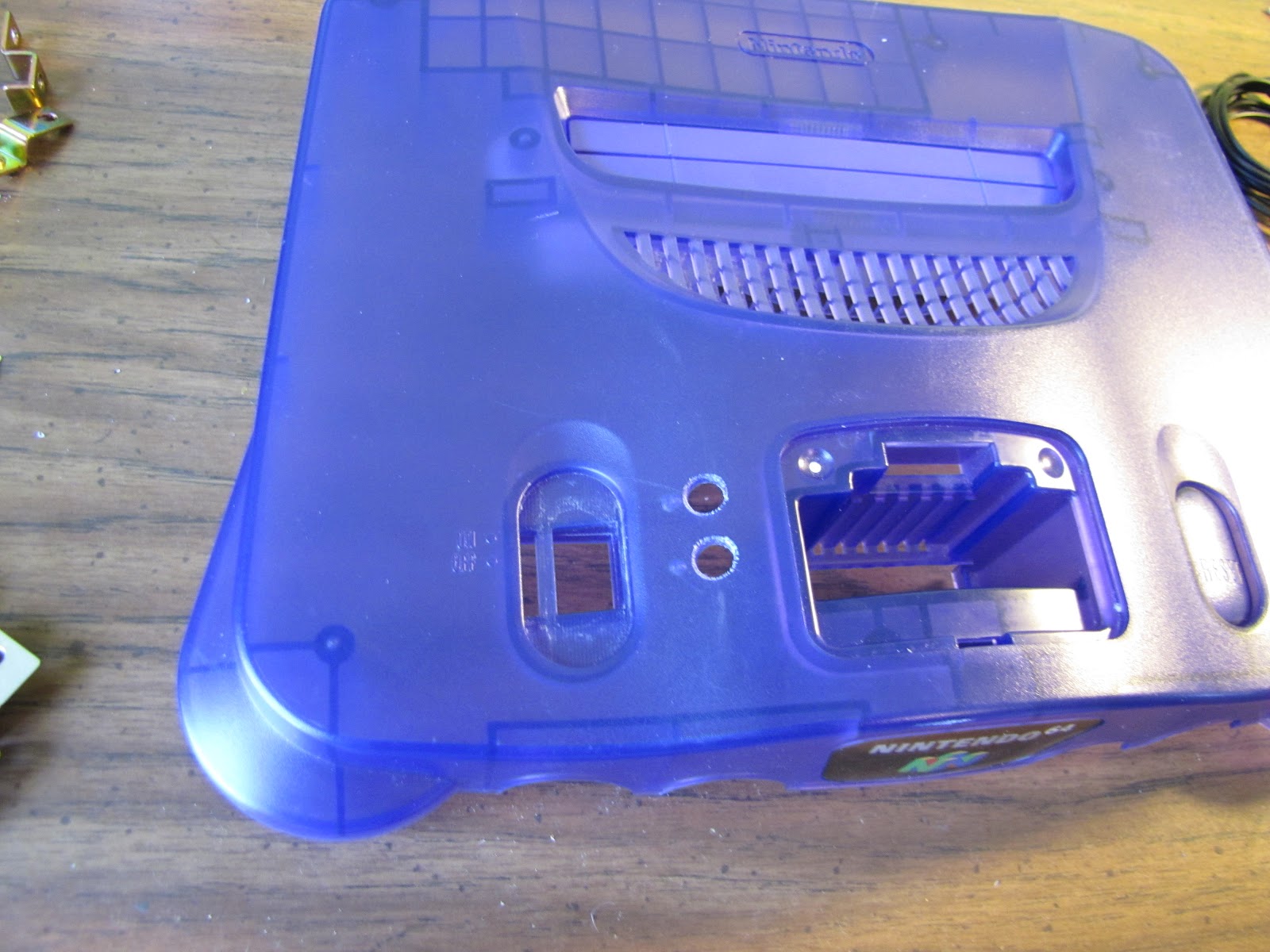
Obviously, you need an N64 too;) For this mod, I chose a transparent "Funtastic Series" N64. It was suggested several places (all claiming to have read somewhere else) that the later CPU revisions found on the Funtastic 64's were somehow more tolerant to overclocking. I can't tell you for sure, because I don't plan on overclocking my Black 64 ever.  |
| It's too sentimental |
So unless someone else asks me to overclock their black N64, I wont be able to tell you. I will say that of all the accounts I read, only one person successfully achieved booting with 3.0X multiplier setting, and I think he may have been using a later Funtastic 64. Yes, I said "later Funtastic" as in, board made in yr2000 or later. Of course, the 64 I used ended up being a 1999 model.
I used the security screwdriver from an earlier exploit to open this 64. I'll be honest, my projects rarely (never in my memory) go perfectly. I broke my security bit, and had to refashion it. Fortunately, I had better Dremel tools this time, and a sturdier bit emerged. Here is its handiwork.
 |
| That's a bodacious heatsink |
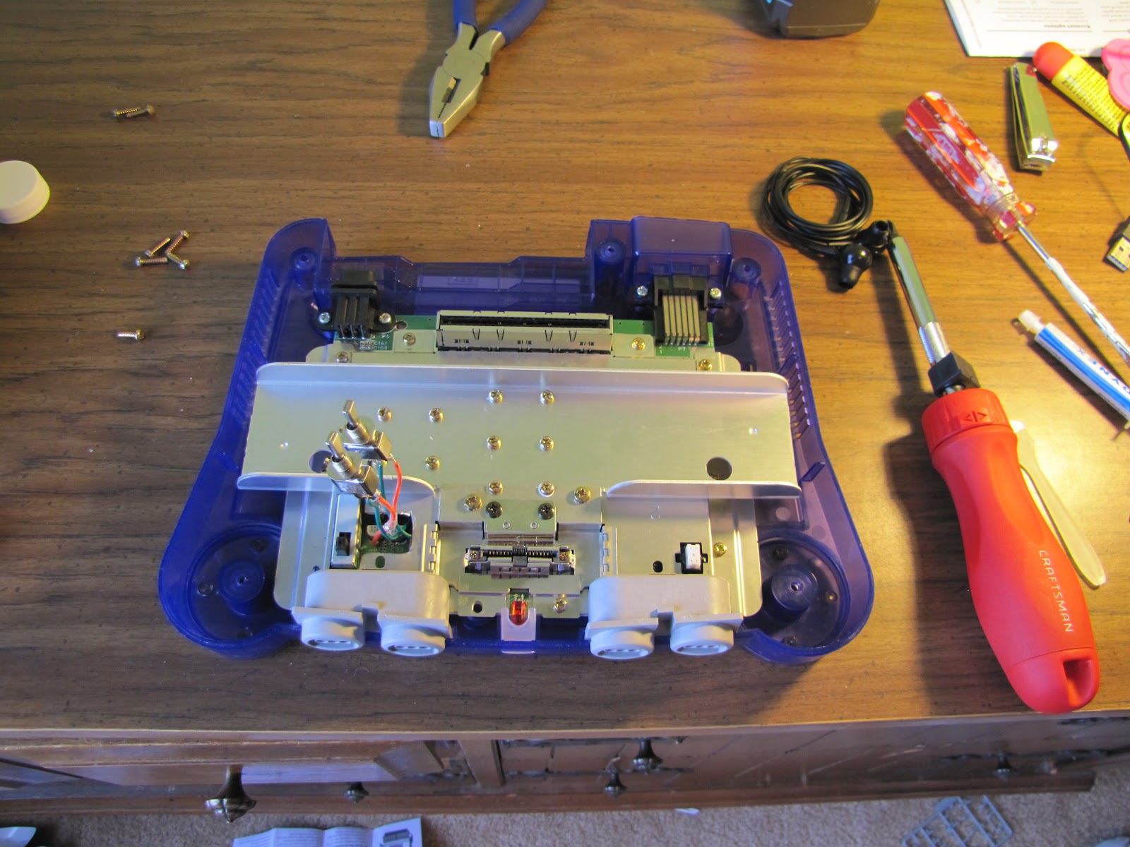
So after you are done removing all of the screws from the heatsink (and the couple around the expansion pack slot), proceed to the next layer (radio shielding). Once all that's gone (and if you take the cartridge slot off, for uhm, cleaning) it should look like this.
 |
| 1999, NUS-CPU-08-1 |
The chip we will be working on is the one of to the left there, just North by North-East of the power switch (if I have to explain what/where the power switch is, stop everything, slowly turn around and put everthing back the way you found it- this work is not for you). It's got the block of aluminum on it. I'ts right above the "080-4101" stamp. You better know what I'm talking about by now.
Once you can lift the 64 board out (don't forget the screws in the power jack and video jack) it's time to prepare yourself for some precision soldering. You want a well lit, very clean area to work on. Most people suggest anti-static mats and grounding yourself. Don't eat anything that makes you jittery or hands shake. You are going to need some fine motor skills here.
 |
| What did you expect? |
Yes, that's a can of Mountain Dew. Yes, that's pizza. Yes, my "good lighting" is a treble light hanging from a bike lock partly strung through a toolbox. Yes, my "clean surface" is some scrap paper I taped down (actually a great trick/tip).
 |
| I like keeping my wires organized |
Yes, that is a lot (6cubic ft, 30+lbs, approx $100) of potentially illegal fireworks next to my soldering irons and wire nest. That's just how I role. I do it for the same reason I weld naked and cut metal without eye protection. (I don't actually weld naked)
 |
| Check out that lighting! |
 |
| and a very sturdy chair to sit on |
Also, unless you have killer eyesight, you might want a magnifying glass and a way to mount it (you will need two hands free for working, so you can't just hold it). I have a large magnifying glass, that I ended up not using. I couldn't see through it clearly with both eyes open, and I don't like closing an eye to look at/through things (camera's, rifle scopes, etc). I don't know why.
Now here we begin arguably the trickiest part of this project. Maybe not the trickiest, but this is the part where if you spaz out and screw up, it's curtains for the 64.
You need to de-solder two pins from the board, and bend them slightly upwards. They are tiny. This is where you might need a magnifying glass. Be carefully not to break the pins. If you can't solder to them, you can't do crap, and the 64 won't run with them hanging out in space.
To do this, I held my soldering iron in one hand, and a needle in the other. Two quick notes, I sharpened the tip of my soldering iron with a grinding bit (unfortunately, while it was at full heat), and I actually had to shave down my needle for it to fit. (I don't have an electron microscope, so no picture of the needle) First, I marked the two pins I wanted to lift with a Sharpie marker, near the silicone chip. The pins you want are 112 and 116. In non-geek speak, that is the 5th and 9th pin from the right, along the bottom of the CPU.
After I marked my pins, I used my needle to gently lever the pin up (using an adjacent pin as a fulcrum) as I very calmly unsoldered it (by heating the base of the pin/leg). This is clutch. If all goes well, it should look something like this.
 |
| You might need a magnifying glass just too see this. |
Okay, see the two pins that are lifted there? It's kinda hard. Just above the tips of the Black and White "4" and "1" printed on the board. Sorry, they are tiny.
 |
| another almost worthless picture |
So, that's probably the hardest part. Don't, (repeat DO NOT) accidentally break the pins. You will want to kill yourself (soldering iron through eye probably).
If you aren't dead, Next try to solder your wire to the pins. Both of them (duh). Once again, I think I used either 20 or 22 gauge wire. It was kinda stiff, but 22 is a safe bet. I guessed and put 3-4 inches of wire on (pre-bent, so that you don't break the pins bending it). In fact, Until I tell you, be in a constant state of paranoia about those pins. I had a 3 pack (red, green, black) of wire. For clarification, I used the green here.
 |
| Should look like this. |
Now, for a couple reasons (but mostly because I think it's super cool) I put heat shrink tubing over where the wires connected to the pins. You don't need much. You could probably heat/shrink the tubing with the small soldering iron, or some other heating element, maybe even a hairdryer-I don't know. What I do know, is that I use my heavy duty soldering iron for this. It heats up fast, puts out a lot of heat and I've used it for years.
 |
| This Soldering Iron once killed a man |
Okay, now it looks like that because when I was somewhere between the age of 7-10, I severely burned myself with it, and dropped/threw it, cracking the casing. It still works fine however. (because I only judge things how well they perform their primary function, not by how hard they try to kill me)
 |
| I told you heatshrink was cool |
In a brief moment of wisdom, I chose to crazy glue the wires to the board near the chip. I put on a healthy amount of glue- crazy glue isn't conductive, so don't be stingy. This added tons of stability to the wires, allowing me to quit freaking about breaking the pins. I HIGHLY recommend you do this. If you do, you can quit being paranoid about break the pins, you have my permission.
Now, we have to go over some things here. Those pins you just secured? You want to either connect them to 3.3v's or ground. Now, if you have 2 pins, and both pins can be connected to 2 things, that's 2 to the 2nd power- that's 4 possible combinations. Good job. So, 4 combinations, resulting in 4 potential clock rates.
Here's a chart (courtesy of GamesX.com)

Now, that chart is pretty darn re-assuring and all, but (according to me) it's not actually worth freaking out over. What I'm trying to say here is this, "When I wired everything up and actually tried the different modes, the results seemed to be perfectly opposite those in the chart". Now, there is a possibility (a freaking huge one if we're being honest here) that I got my ground and 3.3v backwards. In any case, for the rest of this time, we are going to assume that I'm right. But it doesn't really matter (you'll see later) so don't worry about it.
Your next order of business is connecting crap. I'll specify: I used 2-point, 3-contact switches for both pins. Basically, the pin wire (green) get's soldered to the middle contact (the one that's always engaged), and then the switch allows you to connect the middle pin to whatever is connected to either side (in this case, either 3.3v or ground). Pretty slick huh? You want this for both pins, that way you can switch between clock frequencies to your heart's content. It's really worth the extra trouble in my book.
Anyways, I did this by making this "Y" shaped wire. One wire connects to where I decided to pull 3.3v from, the other 2 go to my 2 switches. I did this for ground also. (using the black wire)
 |
| Pretty obvious what's going on here. |
Just a little tip for building the "Y"'s: I put tiny little hooks in the ends of the wire, and soldered as they hung from the "stem". Granted, I burned my fingers (turns out heat transfers through metal) the first time. The second time I held the plastic with some pliers, which in turn became deformed (I think my soldering iron is fueled by my stupidity. just an estimation). So, the best way to do this would be holding the end (the exposed wire, opposite where you are soldering) with the pliers, and soldering the intersection.
Now, there's something I've neglected to tell you up to this point, and that is simply, where the heck do you get the 3.3v and ground from? Well, this is something I couldn't figure out for a while, so bear with me. I originally wanted to take my power and ground straight from the power switch, but that started looking difficult to do (due to the shielding around the switch). Also, a recently gained understanding of circuitry (courtesy of Physics 222 at Iowa State University) made me kinda nervous to do so, lest I draw more amps than I wanted and fry the chip or something. So, after scouring the internet, it seemed to be universally accepted that you could take both 3.3v and ground from the small capacitor (the shiny metal cylinder with the partly black top) at location C81. Now, depending on what year your 64 was made, C81 could be in a couple slightly different places. Whatever, it doesn't matter. In general, it's to the right of the power switch, and south of the CPU (basically where you want it to be). The south end of the capacitor is supposedly 3.3v, and the north end ground. Hence me soldering the red (looks orange) "Y" just below ("left" in this picture) the capacitor.
 |
| This is where things start looking "non-factory" |
Do the same thing for the ground, but put it on the other side of capacitor at C81. In case you haven't figured it out "C81" literately written on the board in white, just below the capacitor.
I put heatshrink (transparent this time) over the intersections of of my "Y"'s so that they would not accidentally contact each other.
 |
| We probably voided the Warranty. |
If you got all that done, congrats, you are on the home stretch. Well, for this half of the mod. We are still going to have to talk about cooling the system, but not today.
Anyways, go find that shielding that goes over the top of the board. To put everything back together (and be able to take apart again later) you are going to need to cut a chunk out of that shielding so that the switches (and their respective wires) can fit through. If you can't really picture what's going on here (how it all fits when the 64 is put back together) don't give yourself a headache over it. That crap is my God-Given talent.
 |
| Yeah, that piece of metal |
I'm not going to over explain this part. Using a a sharpie and a Dremel, I cut a chunk out of the shielding. That's pretty much it. Grind the edges of the cuts so that you don't accidentally cut the insulation of the wire with it.
 |
| ready... aim... |
\
 |
| Fire! |
Once I was sure I'd be able to fit both switches through the hole, I started soldering them up to their respective wires. Once again, I started by putting tiny hooks in the ends of the wires, so that I could hold them in place with one hand, and solder with the other. (I do own an elaborate soldering assistant complete with all manner of arms and adjustments and gator clips, etc but it's just gets on my nerves) Plus, the "hooks" method is stronger in the end. Oh, and I held the CPU's pin-wires with pliers while I cut and stripped them to match the length of the 3.3v and ground. Even though crazy glue is usually a safe bet as far as strength goes, it's not worth the risk at this point.
One other thing, I wasn't totally sure about the length of any of these wires. Given the curvy (sexy) nature of the N64 case, it was kinda hard to estimate the required length for all of this (I didn't try very hard in any case). My wires ended up being a little long, but it wasn't such a big deal. In the end, you can creatively bend stuff so that it all fits (as you will see later), but I do wish I would have made my stuff a little shorter. My wire was kinda stiff, so bending stuff around later puts unwanted strain on all the solders, and could potentially cause a short or disconnect. Just a forewarning.
 |
| Antennae? |
Uhm, keep track of which switch goes to which pin, and try to keep 3.3v and ground on the same side for both switches. This will make figuring out what switch combinations produce what multiplier a lot easier later. Or now. At this point I took the 64 inside and cobbled it together (carefully) to make sure that things were in mostly working order. There's no point to continue until you get this part right.
*********************Switching Gears for a Second Here**********************
Some things to keep in mind, everything is still delicate, so be careful. I used two hands when operating each switch, so as not to strain the solders too much. I set the board into the bottom half of the case, which makes connecting the power supply a lot easier. Because I removed it earlier, I had to put the Game-Cartridge socket back on the board. There's no plastic support, so be careful when putting a jumper or expansion pack in, and mounting the game cart. Because the whole shielding/heatsink is not on the board, you need to be careful, and not run the 64 for very long. I operated mine for 1-2 minute sprints. Just long enough to verify that the machine boots. With a game that has sufficiently long, 3D intensive title screens (I used Perfect Dark and Episode 1 Racer), you should be able to see a noticeable difference with the different multiplier settings. You can figure out what combinations does what later. (with a stopwatch or something) All you care about right now is that the machine boots for at least 3 of the 4 possible combinations. Almost nobody gets 3.0X multiplier to work, so don't sweat it. Also, I powered down the 64 before switching the multiplier. I'm not sure what would happen if you flipped a switch during operation, but I can't believe it's worth the risk to find out.
******************Back to Construction*****************************
Also, not a huge deal, but my switches were keyed and came with little washers that had a single tab to keep the switch from spinning in their hole. Not a huge deal, but as I wanted to be able to still disassemble my 64 later, I didn't want to resort to crazy gluing this time.
 |
| Logical placement of the switches. |
Now, on the underside, where those little washers are going to go, you need to smaller holes for the little tab to fit into (to keep the switch from spinning, remember?) Sorry I don't have better photos of this part. In any case, I drilled small holes just deep enough into the case for the tabs to fit. I didn't want to go all of the way through, so it took some finessing. Not easy with my rather large power drill. If you're stupid like me, large, strong, and steady hands are necessary compensation.
 |
| See the little indents next to the holes? |
I accidentally put my switches just barely too close to each other, and the previously mentioned washers were hitting each other. So I shaved them down on the conflicting sides with my dremel.
 |
| There is a mini story about those cuts that I'm too tired to go into. |
You are now basically ready to begin re-assembling everything. Okay, for reasons explained later, I put thermal paste between pretty much everything from the various CPU's (all 3) all the way up to between the shielding and the heatsink. That's pretty much it.
 |
| Everything is screwed on. |
If your wires are a little too long, this will probably happen.
 |
| Whoops.
I had to carefully, and I mean C.A.R.E.F.U.L.L.Y. bend the wires so that the switches would be closer to their final location.
|
 |
| Something like this. |
There's not a whole lot of clearance, between the power switch and the internal casing for the Expansion/Jumper Pack, but while it's inconvenient, it just looks all the cooler later.
 |
| The top of the console is obviously sloped too. |
If everything works out, you pull the switches through the holes, and put the little nuts on them to keep them from sliding back down, and you are basically done (sans the security screws that go on the bottom).
 |
| Sexy |
 |
| very sexy. |
And some shots with my slightly modified Expansion Pack (explanation some other day)

 |
| My favorite Picture. |
Now, you can obviously enjoy playing the 64 some, but I wouldn't play it overclocked (except for short periods) for now. Even if you thermal pasted like crazy (like me) N64's stock heatsink is not made to handle the extra heat generated by overclocking, and too much O.C. time could fry the 64, permanently.
So, please have patience. I'm still trying to consider what I'm doing long-term for cooling. It's not easy, but I promise not to leave you hanging.
Because I obviously didn't go into detail on any soldering techniques and some of the other construction skills used here, if you have any questions about how I performed anything here, feel free to leave a comment or email me at e.dakotalee@gmail.com
*All the stunts you saw performed here were done without any measuring tools or parental supervision.*
This Mod is Based Primarily off the information on this site: http://www.gamesx.com/misctech/n64oc.htm
The switching setup I used is from this site (the site is otherwise useless or inaccurate): http://kyorune.com/modding/article.php?id=70
This was the only forum with decent information: http://nfggames.com/forum2/index.php?topic=242.0
4 comments:
The best part of your blog (keep in mind that I have no tech bones in my body) is the photo with the frozen pizza and the throwback Mountain Dew (which is a perfect beverage choice when working on a classic like a N64)!
Well done! The fact that you waded through archives of the Internet's gaming community is proof enough that you're dedicated to this project, but setting up this indepth documentation deserves some serious respect. It's got to be one of the only step-by-step guides out there!
Anyway, as for the results, the switches' placement just looks too good, like it was meant to be, and the fact that it actually boots is.. kinda surprising! Overclocking PC's is one thing but overclocking a decade old video game console is quite another.
Nice job.
(btw, liking the open bottle of H2O2 just chilling in the background of the last few pictures)
Thanks a lot man! Yeah, I use the H2O2 for cleaning pretty much everything especially the game carts(and as mouthwash). Just kidding, I use rubbing alcohol for mouthwash.
10 [URL=http://www.okay2shoes.net][b]Jordans Shoes Online[/b][/URL] Mistakes That Outdoor Personal Trainers Make
Training people outdoor signifies that you'll want a change of clothes, waterproofs, intensive exercise apparatus and an extensive first help kit in case of any mishaps 6.Now not properly recording shoppers progress being outdoor signifies that its not really easy to carry a clipboard to record results.So you want to make sure that you report your clients growth on an excel spreadsheet so you'll proceed to progress them 7.No longer taking their own well being and effort ranges into consideration its one [URL=http://www.okay2shoes.net/nikeairmaxnikeairmax97womens-c-3_58.html][b]Air Max 97 Women[/b][/URL] thing being indoors but if you have to take every client operating, it will drain on you after a time although its smartly below your personal pace.Arrange so you don't need to run with them every time 8.Now not taking into account gas prices and additional advertising costs sure you're not paying hire but you additionally don't get access to the huge quantity of prospective shoppers that gym based totally personal trainer shoes do, so it is very important up your spend on promoting.Plus you wish to have to travel in your consumers so that you'll spend more on gasoline, additionally allow for the fact that you won't be able to do as many sessions in a day as a gymnasium based totally pt would as a result of the travel time 9.Simplest doing one to at least one sessions doing a boot camp and it provides now not solely an additional income, it also advertises you as an individual teacher to permit through, a super technique 10.Now not being correctly certified operating outdoor means that if in the united kingdom you'll want to get your tide(Coaching in numerous environments)Qualification, plus, suspension trainer, kettle bell trainer and so forth.If you don't seem to be qualified, you aren't insured.Not the most professional way to run a personal training business.
Post a Comment